| |
What is IRM?
Interference Reflection Microscopy is the imaging of interference patterns created by the thin (on the order of a fraction of the wavlength of light) spaces between thin films, such as the space between a coverslip and an apposed cell membrane.
Selected AIF publications including this technique are:
Why IRM?
IRM is useful for looking at a cell's adherence to a substrate. In the example below, most of the black spots within the perimeters of the cells are contact points where the cell is adhered to the coverslip subtrate. However, analysis can be compliated by membrane pushing against the substrate which is not adhered or by interference fringes produced by structures even multiple distances away from the substrate.
MTLn3 cells plated on a #1.5 coverslip fixed and stained for f-actin with
rhodamine phalloidin. The image at left is IRM. Center is f-actin. Right
is a merge. Olympus IX 70 microscope with 50/50 mirror in epiillumination light path
and a 40X adjustable iris objective. Central cell is approximately 40 um from top to
bottom. |
For a published example from the AIF, please see Bailly M, Yan L, Whitesides GM, Condeelis JS, Segall JE. (1998) Regulation of protrusion shape and adhesion to the substratum during chemotactic responses of mammalian carcinoma cells. Exp Cell Res. 241(2):285-99.
IRM is a subset of general reflection microscopy which is underutilized in biological applications. For an example of its use to generate 3D images of assembling matrix proteins in vitro, see A. O. Brightman, B. P. Rajwa, J. E. Sturgis, M. E. McCallister, J. P. Robinson, S. L. Voytik-Harbin. (2000) Time-lapse confocal reflection microscopy of collagen fibrillogenesis and extracellular matrix assembly in vitro Biopolymers, 54:222-234.
Comparison of IRM with standard epi-illumination and with confocal
 A. |
 B. |
In A., IRM was performed with an Olympus IX 70 microscope with a 60X adjustable iris objective, with the field diaphram and mirror block offset to opposite sides of the field to remove a central reflection, and with detection by a Cooke Sensicam. In B., IRM was performed with a BioRad Radiance 2000 laser scanning confocal microscope with polarizing filters to remove a central reflection and to allow for imaging across the entire field. This is more simple than IRM on an epifluoresence microscope where typically we offset the field diaphragm to one side and have to close it which limits the field of view. As you can see in A above, the image is clipped in the lower left and the illumination is uneven across the field. Also, to generate contrast on the standard epiillumination system, the iris diaphragm on the objective must be partially closed which reduces the N.A. and, thus, at least theoretically, resolution. On the confocal, the full N.A. 1.4 (or as much of the back aperture as is filled by the laser) of the 60X objective is utilized and achieving even illumination across the field typically is automatic.
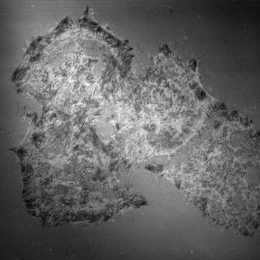
 This is not an IRM image. This is the
bottom of a pancake (approx.12 cm in diameter) cooked in sizzling bacon fat on a hot
skillet. The dark areas are where the batter was in direct apposition to the
substrate. This is not an IRM image. This is the
bottom of a pancake (approx.12 cm in diameter) cooked in sizzling bacon fat on a hot
skillet. The dark areas are where the batter was in direct apposition to the
substrate. |
Another excample with hela cells fixed and stained for tubulin: