
| |
 Background:
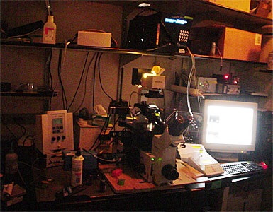
Digital Station #5 was purchased with funds on a Shared Instrumentation grant in 2002 to meet the needs of high speed digital imaging of dual labeled particles moving in cells (e.g. CFP/YFP or GFP/TexasRed) and to perform ratio FRET (especially CFP/YFP). Instrument is also used for long (6 to 18 hours) time lapse sequences. Example publications with data from this instrument:
Instrumentation:
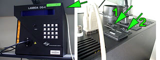
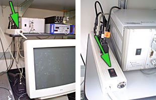
Sensicam QE air cooled CCD camera; I.P. Lab Spectrum running on a PC; Sutter DG4 for excitation; ASI filter wheel for emission; alternate DualView for emission; Uniblitz shutter for transmitted; piezo for 100um travel of focus; ASI electronically controlled stage; forced air or air/CO2 heated chamber.
Instructions:
Unlike other microscopes in the AIF, Digital Station #5 does not have a single standard configuration you can expect to find the system in every time you begin to work. Therefore, you need to check that the instrument is configured for what you need.
Before Turning On, Install the Microscope objective lens.
You may not turn the microscope nosepiece to change objective lenses. The lens must be changed manually by unscrewing it and screwing in the correct objective.
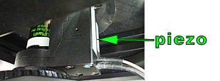
Make sure all electric power to the microscope devices is OFF before
changing the objective. This is important because you do not want to break the piezo
(the little box next to the objective) or the stage.
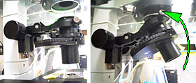
Tilt the condenser back (or remove it completely).
Take the stage plate off.
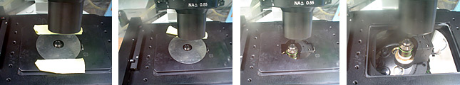
Remove and replace the objective.
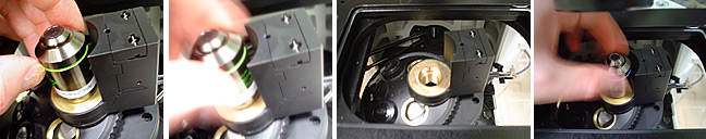
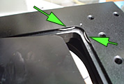
Put the stage plate back in. There are metal springs in the
back right corner. Push the stage plate down at an angle into the corner springs and
then press the plate flat into the stage.
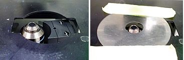
Note that the piezo is off center. The top stage plate must be
placed off center as pictured.
Tilt the condenser back down (or put it back in).
Filter Blocks.
The microscope should always be left with a JP4 CFP/YFP filter for ratio FRET in turret position C.
Any changes in the filter blocks will be written in a table on the wall.
This is the configuration as of 28 March 2008. However, except for the JP4 CFP/YFP filter, this may not be the actual configuration the microscope is in!
Filter turret in microscope (as of Jan 30, 2008):
| Turret Label | Name | Excitation | Emission | Dichroic |
| A |
FITC | |||
| B (green tape) |
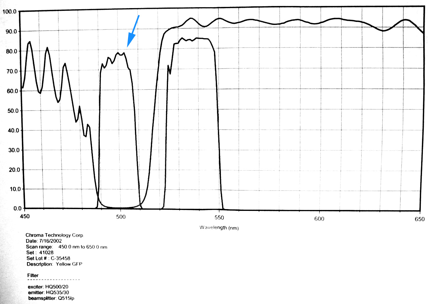
CFP/YFP 51017 BS&M for use by eye |
(none) | approx. 450 to 485 and 530 to 570 nm |
51017bs (see Chroma website for spectra as ASCII) |
| C (red tape) |
CFP/YFP 86002v2 JP4 cannot use by eye! |
(none) | (none) | 86002v2 (see Chroma website for spectra as ASCII) |
| D |
Cy3 |
The standard configuration is
In early 2008 maintenance on the instrument was done. The following changes have been made.
| Component | Old | Date changed | New |
| Emission filter in DualView | Chroma 465/30 | 20080326 | Chroma 470/20 |
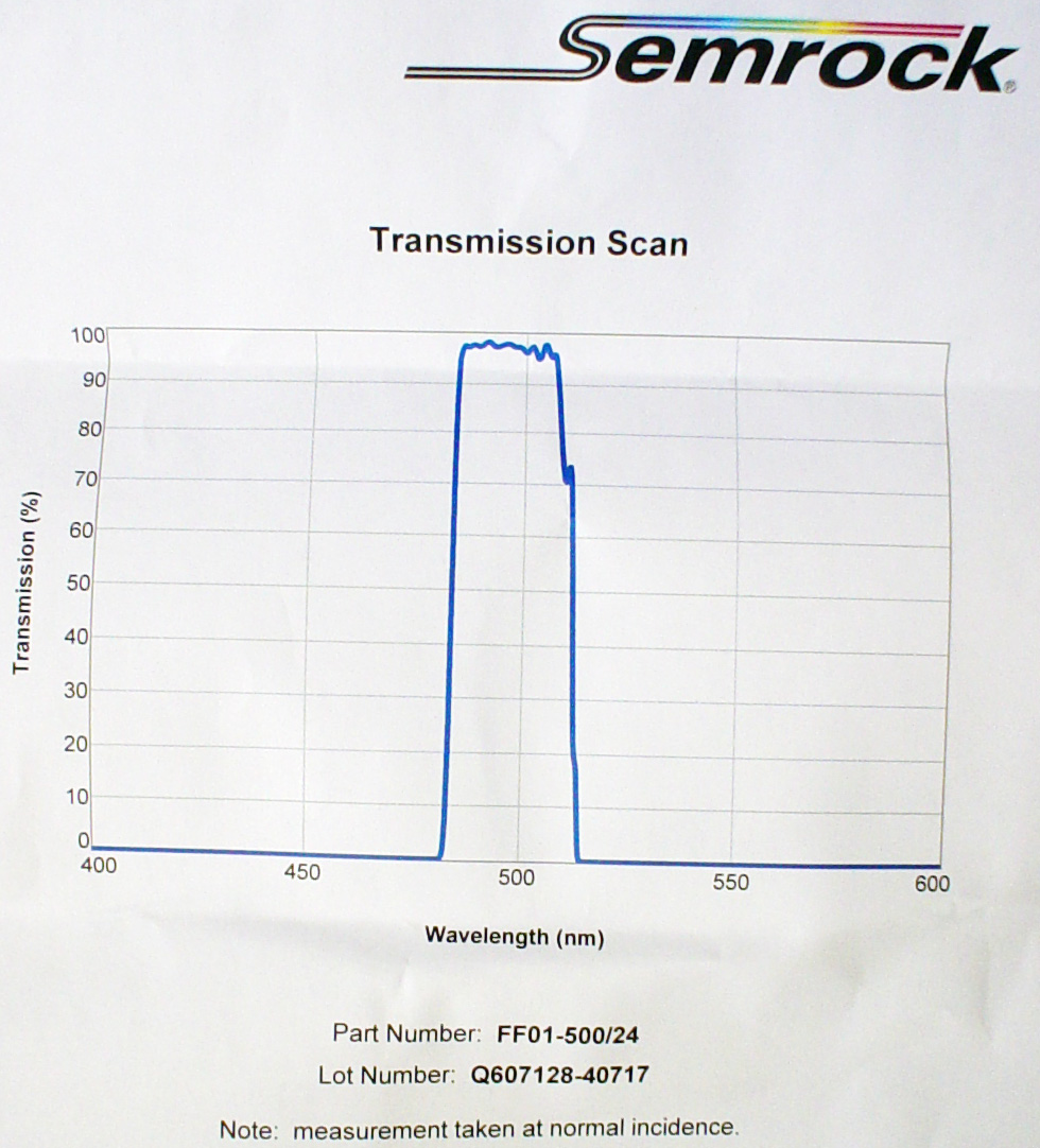
| Excitation filter in Sutter DG4 position1 | Chroma 430/25 | 20080328 | Semrock 434/17 |
| Excitation filter in Sutter DG4 position2 | Chroma 500/20 | 20080328 | Semrock 500/24 |
Filters changed in the DG4 sliders should be labeled at the outer
edge of the slider.
Environmental Chamber.
(Instructions on separate page. Click here.)
Basic Startup.
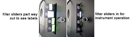
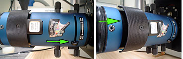
To image normal full frame, the DualView unit between the microscope
and camera must be set to "Full View" and have the filter blocks pulled out one
click as pictured.
What is the DualView? Dual-ViewBrochure-11_02.pdf and http://www.optical-insights.com/micro-imager.html
Official alignment instructions: DualView-alignment.pdf
Dynamic range of the cooled CCD camera is 0 to 4095. Images are not rescaled to 0 to 65520.
The function keys are clearly labeled. If you are used to
using other AIF instruments, you will need to note the different function keys here.

Basic Shutdown.
Ratio FRET on fixed material.
There are scripts for automating the collection of ratio FRET images.
Each time the script is run the following images are collected and stored in a directory named the time of image collection:
DualView alignment instructions.
http://www.aecom.yu.edu/aif/instructions/ccd5/DualView-alignment.pdf
 Filter specs for CFP/YFP.
The filters we have for the DualView are:
505dcxr D465/30 HQ535/30m (CFP/YFP)
565dcxr D480/40 D630/50 (CFP/RFP)
Michael's scribbled notes:
o Green tape of alignment slide up
o Koehler brightfield
<Shift>F10 is alignment script.
run script
hit return
between yellow lines
stop = <shift>F9
say No to get ratio image of grid.
These dual excitation and dual emission filters were
removed from the 51009 F/Cy3 block for dual imaging of red and green dyes. The filter block was then installed in the microscope. To excite green or red individually, either the exciter in DG4 #2 or #4 position is activated. To image green or red individually, the correct filter position in the external ASI wheel is selected or the green/red DualView insert is used. |
The image is displayed on the camera as follows when
the DualView and camera are in the below configuration.
|