| |
| Instructions for Leica AOBS confocal microscopy |
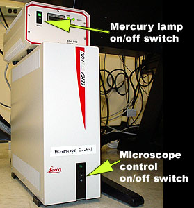
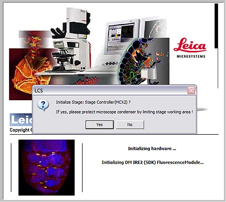
Startup
Please follow these steps in the order listed.
Sign into the logbook.
Scanning and Imaging:
The Controls:
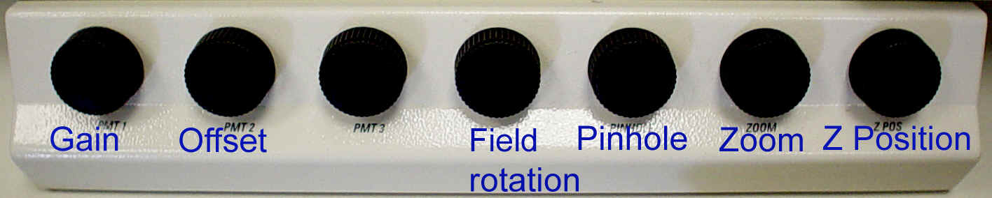
Using the Controls:
1. Gain: Initially the image will probably not be present, making it necessary to adjust the gain initially. Most folks will end up setting the gain levels in the 500-900 range out of a possible 1000.
2. Z-Position: The specimen may simply be out of the confocal plane, adjusting the Zpos knob to move it may make the live preview much brighter. It is important to clearly focus visually on the sample before switching to the scan mode.
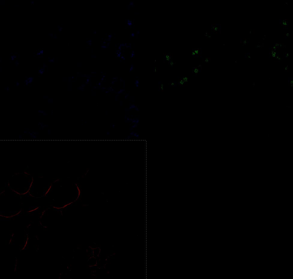
3. Qlut: To monitor the range and the offset level it's best to use the Qlut button which uses a lookup table to display pixel values. The table uses a range of green-white-red-blue for the pixel intensity (0-255). Images should be set so that the brightest pixels in an area of interest are nearly blue or saturated. (See the Picture below.)
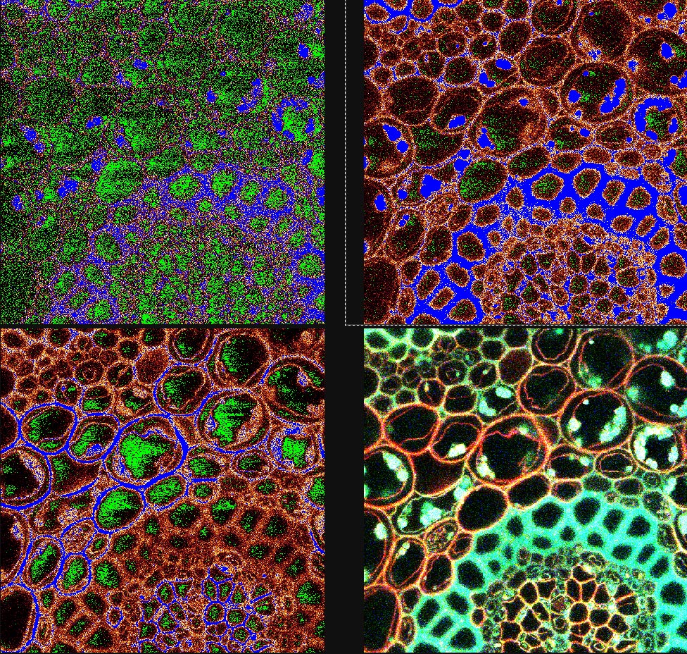
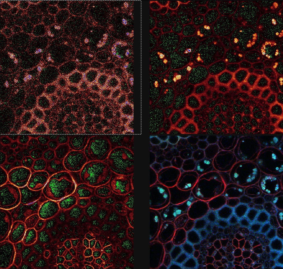
4. Offset is the black level of an image and may be viewed by the QLUT as green. The image should not contain any green in areas where there is a signal and the green should be adjusted for most imaging such that it is speckled and not solid. Setting the offset too high will cause the loss of low-intensity signal and should be avoided.
5. Line Average: This should be used to capture all final images with reduced noise. Setting the line average to either 4 or 8 lines seems to be adequate for most use. While it has not been looked at quantitatively we think that the 16 line average doesn't provide much improvement on 8 lines, especially when the time require for aquisition is considered.
*Alternately, Frame Averaging may also be used, in doing so the microscope scans the full frame multiple times and averages those full frames.
6. Zoom setting: Zooming in on the image will allow the user to capture an image with much greater detail and seeing the smaller structures in a sample. It is important that one doesn't zoom beyond the optical resolution of the scope. To read more about zoom settings see the optimal zoom settings calculated 12/03.
![]()
7. Pinhole: Most users should not change the pinhole diameter. The Leica software will automatically adjust the pinhole to equal 1 airy disk which is optimal for confocal imaging. Opening it will allow a brigher signal but will reduce the z resolution by collecting
Adjusting the Display and Saving Data.
![]()
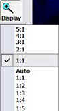
1. Display: Adjusting this button will allow the user to view the entire image on the display (Auto) or as the image exists (1:1). The setting of 7:1 will display each voxel (Voxel is the term used for a 3 dimensional computer pixel.) As the confocal takes optical sections the data is collected as voxels not pixels.) as seven pixels on the screen, whereas the setting of 1:7 uses 1 pixel of the display to represent 7 voxels. The display setting directly effects the snapshot.
2. Snapshot: To save the display image as viewed on the screen you may rightclick on one of the channels then: Send to > Experiment > All Snapshot.
3. Saving: Images should be saved immediately after acquisition to avoid loss of data collected over long periods of work. Initially it is neccessary to set the directory and create a name for the files to be saved within an experiment. This name will be used to create a folder within which the images and a text file containing the instrument parameters used during collection.
Tips:
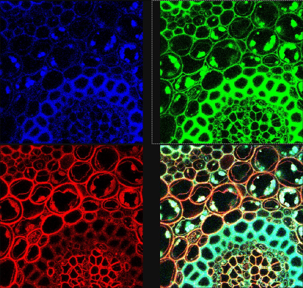
When multiple labeling, you should check for spill over from any shorter wavelength channel into any longer wavelength channel (especially from the green channel into the red channel). You must use the sequential imaging mode if there is spill over. Leica printed this bulletin in November 2002 to describe sequential scanning.
Images should be collected via the Single Scan button with line averaging or frame averaging set.
Zooming should be set to see the features of interest without oversampling. [More here.]
Keep in mind that the Format button sets the number of pixels comprising the image and the resolution of the raw data. But the image you see on the screen may be zoomed or shrunk (with loss of resolution) if the Display is set to Auto.
Shutdown
THIS IS A CHECKLIST; MAKE SURE EACH STEP IS FOLLOWED!

Optimal scanning magnifications have been calculated by based on thegr literature from Leica and the formulae in Jim Pawley's Handbook of Confocal Microscopy. Click here for the Excel spreadsheet.
Other tidbits:
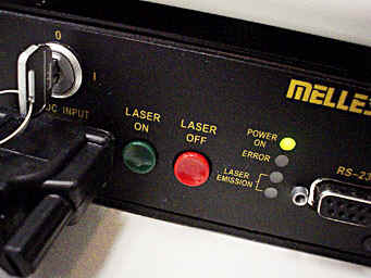
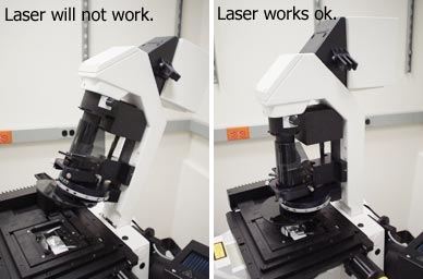 If you can't get any laser through the system, make sure the illumination pillar is in its upright position. When it is tilted back, the laser illumination path is shut. |
||||
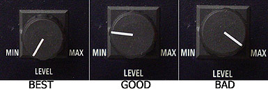
| Keep the laser turned low! We don't
want to burn it out. For normal imaging with 458 to 514 nm light the laser should be kept between MIN and the noon position. If you turn the laser to MAX for bleaching or uncaging, make sure you return it to a low power position as soon as you are done. |
||||
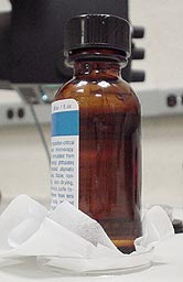 Please be sure to place the
immersion oil in the petri dish top or weighboat. Please never put the oil down on a
table, mousepad, etc. This really simple step will keep everyone who uses the microscope
happy and your clothes from getting oil on them. Please be sure to place the
immersion oil in the petri dish top or weighboat. Please never put the oil down on a
table, mousepad, etc. This really simple step will keep everyone who uses the microscope
happy and your clothes from getting oil on them. |
||||
| If you are experiencing problems with horizontal lines while using the weaker (especially 458nm, 476nm) laser lines? Try to clean up noise using fft post-processing. | ||||
|
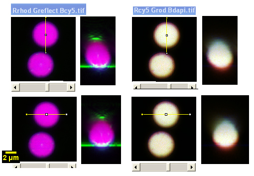
4um Molecular Probes Tetraspeck beads look skewed to one side due to a problem with the optics. Also, if doing critical; colocalization, watch out in the Z axis for chromatic aberrations.
Examples of images from this microscope here.
If you have problems using these instructions or would like more information on confocal at the AIF please contact Michael at cammer@aecom.yu.edu.