BioRad Radiance 2000 Scanning Laser Confocal
Microscope notes on proper usage.
Software last upgraded to version 4.1 of on 25 May 2002 |
| TABLE OF CONTENTS:
|
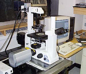 BioRad Radiance 2000 confocal
mounted on a Nikon Eclipse epifluorescent microscope. |
BASIC RULES:
- The air conditioner must ALWAYS stay on the room gets cold, if you get cold
easily you may want to bring a sweater.
- When you are done working, please leave the working area clean.
- If the next user is physically present leave on the
lasers and the HG arc lamp, otherwise shutdown the lasers.
- Only shut off HG lamp if you are the last user or no
users are signed up for at least two hours (weekends).
- Please follow the sign-up rules.
- If there are any equipment problems please
notify the AIF staff by email or leave a message at x2890 or x3547.
- Make sure to move your data off the confocal computer at the end of the
session. It is advisable to make at least one archival copy of
your data. The archival copy shouldn't be not be used for regular
access.
FORBIDDEN:
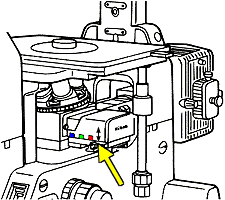
- Don't touch the confocal unit mounted on the left of the microscope.
- Don't turn on the mercury lamp if the confocal is already on.
- Don't use so much oil that it drips down the side of the microscope
objective.
- Don't use equipment until you have signed into the log book.
ABOUT THE OBJECTIVES:
The standard configuration of the microscope, these lenses should always be installed:
Never use the following air objectives with oil:
- Ground glass prism for centering laser beam;
- 10X phase 1 (yellow ring);
- 20X brightfield (green ring);
- Sometimes on the microscope: 40X long working distance phase (adjustable collar) not recommended for confocal.
Always use immersion oil for these lenses:
- 40X planapo.
- 60X phase 4 (darker blue ring).
For transmitted light images, the condenser should be set for the "0" (or
"A") position or the phase objectives should be matched with the correct phase
ring. For instance, the correct setting for the 60X objective for pseudo Nomarski or
D.I.C. is "0" or for phase contrast "Ph3".
Proper usage of 60X oil immersion objective:
- One small drop of oil on the coverslip (slides) or in the center of the
objective (culture dishes).
- This one small drop should be sufficient for scanning a few slides.
- Do not let oil cross the white ring. No oil should ever run down the side of the
objective.
- If there is oil on the side of the objective, you are using too much oil!
- To clean glass surface on top of the objective, lightly drag lens tissue without applying
direct pressure.
- To clean the sloped metal surface around glass, use lens tissue with light pressure and wipe
up to prevent oil from getting on side of objective.
Once oil has been applied to the 60X objective and to a slide, before switching to a
lower power objective oil must be cleaned off both the objective and the slide. DO NOT
GET OIL ON THE NON-OIL OBJECTIVES!!! We repeat, DO NOT GET OIL ON THE NON-OIL
OBJECTIVES!!! We repeat, DO NOT GET OIL ON THE NON-OIL OBJECTIVES!!!
ABOUT THE FILTER BLOCKS:
For labeling with single fluorescent probes, the following applies.:
- Excitation at 488 nm. Emission above
500 nm. (Narrow pass and long pass available)
- Excitation at 547 nm. Emission above
560 nm. (Narrow pass and long pass available)
- Excitation at 647 nm. Emission
above 660 nm. (Long pass)
Triple labeling is done with dyes that are in the following
families; this list is not exhaustive. Also, dyes that excite at 488 but emit in the
Rhodamine range can be used, but only with Cy5 as a second dye.
- FITC, Cy2, Alexa488, Ca Green, Fluo3, Bodipy 488, GFP, eGFP, YFP
- Rhodamine, Cy3, Alexa 547, RFP, propidium iodide, DiI, mitotracker red
- Cy5, Cy5.5
All filters and laser lines are chosen with the Methods selection. The staff
are
happy to write custom method for you. For instance, if you want simultaneous
collection of FITC, Rhodamine, IRM and Nomarski at a 512 X 128 pixel screen size, we can
set this up in a few minutes and save the method as part of your account profile.
For more information about fluorescent probes, visit our probes web page.
BASICS ON USING THE MICROSCOPE
Under the nosepiece (the ring with that holding the objectives) on the right
of the scope there is a slider for
standard epiflourescent imaging.
 |
 DAPI, Hoechst, etc. |
 FITC, Alexa 488 Cy2, GFP, etc. |
 Rhodamine, Alexa 568, Cy3, propidium iodide, etc. |
 phase contrast, brightfield, etc. |
|
The filter block slider must be set to (far right) for confocal microscopy.
(*The filter is somewhat more difficult to move as it gets near the right limit,
so carefully slide it to the right.)
GETTING STARTED:
- Sign into the log book. If you do not sign in, you will lose access
to facility. You have been duly warned.
- Turning on the mercury arc lamp:
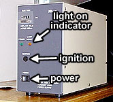
A. On switch from O to |.
B. Pause.
C. Press ignition button.
D. Wait until lamp is on before proceeding.
- Turn on the computer if it's not already on.
- Log on with your user name and with your password. Use "test"
and the standard AIF user password for windows
- Turning on the big power unit (Lasers and Scanhead) to left of table
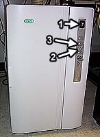
A. Turn on power switch marked "1" (this is the
main power switch)
B. Push button marked "2" (this starts up the
Kr/Ar laser for excitation of FITC and rhodamine)
C. Push button marked "3" (this starts up the
red laser for excitation of Cy5 or for some transmitted methods)
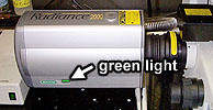
- Wait for green light on front of scan head to turn on and wait for beeping
to stop.
- Run LaserSharp 2000 software.

- Login with your user name and password.
- Choose a method. This is in the Methods menu. Right click on
the desired method and choose "Load" from the menu.
- Set "objective" to proper magnification in the control panel toolbox.
This must be done every time you change methods.
COLLECTING AN IMAGE:
At this point you are ready to view your sample. To use the confocal you must
first locate
your sample by eye through the microscope. You may do this using standard epifluoresence or
transmitted light. Next you will switch to the confocal.
- Most people will use the 60x oil objective, so these instructions are suited
to that application (for air objectives skip the addition of oil.)
- One small drop of oil on the coverslip (slides) or in the center of the
objective (culture dishes).
- This one small drop should be sufficient for scanning
a few slides.
- Be sure that no oil runs down the side of the objective!
- Place a sample on the stage, coverslip down.
- Be sure the beam splitter on the bottom right of the scope is pushed away
from you, allowing light to go to the eyepieces.
- Be sure that the fluorescence slider is pulled to
the far right, to the double arrow (*The
filter is somewhat more difficult to move as it gets near the right limit,
so carefully slide it to the right.)
- Turn on the transmitted light with the power supply located to the right
of the instrument on the bench near the computer.
Don't use the switch ON the instrument.
- Be sure the condenser is set to Ph3 (again, this is for the 60x objective.)
- Focus on the sample.
- If you would like to collect a phase image you must align the condenser
for Koehler illumination.
- a.
Using the lever at top of scope, close luminous field diaphragm (down
position)
b.
Focus the diaphragm image (a brightly lit hexagon) by raising or lowering
the condenser
c.
Center the diaphragm image using centering screws on condenser
d.
Open luminous field diaphragm all the way (This is not a typical Koehler
step but is required for collecting phase images with the Biorad.)
- Turn off the transmitted light
- To quickly view epiflourescence, choose a fluorescent
filter type, using handle at right of instrument.
- View cells by eye. Place
desired cells in center of field -Keep in mind that the Confocal will sample
a square area from the center of the field of view so you should put the area
of interest in the middle of the field.
- Move fluorescent filter to far right position ()and pull lever at right of scope
towards the double arrow. (*The filter is somewhat more difficult to move
as it gets near the right limit, so carefully slide it to the right.)
To Collect a Single Image
- Check objective setting in the control panel tool box.
- Pull fluorescence slider to the far right, towards the double arrow
().
- Pull the beam splitter lever at the right of scope towards you (Confocal
position).
- Turn on the laser by clicking on the blue starburst.
- An image should appear in the main window. (If you don't see anything remember
that the Confocal is collecting and optical section so you may need to adjust
the focus of the microscope.
- Choose the tab for the probe you want to work with (ie. Red, Green, Phase
etc.)
a. Adjust iris diaphragm.
The optimal can be set by clicking round iris button at right of sliders.
b. Adjust laser intensity.
c. Adjust gain level. This
can be sided with the setlut. Ask a staff member.
d. Do not adjust the Offset.
This should always be set at zero..
- Repeat for other probes, if necessary.
- Viewing phase contrast requires the splitter button to be selected (for
imaging) and de-selected for viewing through eyepieces.
- Stop scanning by clicking the blue starburst again.
- Choose the Kalman mode.
- Change N, number of scans to 8.
You can also use 2, 4 ,or 16.
- You must use the arrows to adjust the N.
- Use the Starburst to scan in Kalman mode.
- The scan will stop by itself, and you may save the single optical section.
- To save image right click and choose export (click here
for more details) Read the section on saving files below>
To Collect a Z-series
- Collect a single image and be sure it looks good.
- Turn on focus motor, at the bottom left of the tool box.
- While the focus motor is on it is critical to avoid using the manual
focus knob, doing so could permanently destroy the focus motor!
- Begin scanning.
- Using the focus motor, move to the top or bottom of the sample, or area of
interest.
- Set the Stop
- Using to focus motor, move to the other end of the sample or area of interest.
- Set the Start.
- Adjust the step size if desired.
- Stop scanning.
- Choose Kalman mode and set N.
- Press the Z-series button, it looks like 3 stacked blue pages.
- Check the enable Z-series box. The focus motor information will be transferred
- Check the collection information. If the time required is excessive,
make changes. These could be increasing the step size, or decreasing
the total depth of the collection.
- Press start.
- Close image box and click YES to save, be sure to save as Biorad file
format. Read the section on saving files below>
- These data can be easily opened and manipulated in
NIH-Image, Scion Image, ImageJ, IPLab or VoxBlast as a 3D volume if desired.
Saving Files
- Any time you want to save an image as a TIF or BMP file, right click on the image with
the mouse and choose Export. More explanation here.
- To save a time lapse series or a Z series, simply click on the X in the upper right of
the window, answer YES to the question whether you want to save the data, and provide a
folder name for the data. More explanation here.
BASICS FOR SHUTTING DOWN:
- Exit the Lasersharp software either by File|Exit or by clicking on the X
in the upper right.
- Do not save experiment (But be sure that you have saved your files!)
- Transfer your files to another computer or burn
a CD.
- If the next user is waiting to use the instrument, leave the machine
on. If not, turn off power switch "1" on the big power unit
to left of table.
- Clean oil off the objective. Drag a piece of lens tissue across the
glass surface. Do not apply pressure with your finger
directly to the glass surface of the objective. You may lightly
apply pressure with you finger only to remove oil only from the sloped
metal sides of the objective. Do not use any solvents; any cleaning that requires the use of solvents must be
done by the staff.
- Leave either the 10x objective or the prism in place.
- Clean the microscope area and remove all of your stuff.
- Log out of your computer account. Either Ctrl-Alt-Delete and Logoff or
Start|Logoff and Logon as another user.
- If it is during a weekday, leave the mercury lamp on. If you are
working at night or the weekend AND nobody is signed up after you, turn off
the mercury lamp.
- Sign out of log book.
HOW TO SET UP DISK :
It has always been policy of the AIF that users
are responsible for their digital data.
Your account is set up in one of two ways. Either 1.) you save your data in a
"data" folder on the desktop or 2.) you save your data in a directory with your
name on drive F:. Files stored anyplace else may be summarily deleted.
If you are an expert computer user and can tolerate the reduced performance due to the
data transfer rate via ALNET, you may connect to another computer to store files directly.
We will keep files on the hard drive until the disk approaches being full at which
point we will begin deleting files. Therefore, take seriously the need to leave time
at the end of each data collection session to move your files over
the net and to delete your old files at the beginning of each new session.
THERE ARE TWO WAYS TO SAVE IMAGES TO DISK:
Valid file names may include the following characters:
"A" to "Z"
"a" to "z"
"0" to "9"
"-" "_"
" "(space)
Do not use any other characters. No periods, slashes, plus signs, etc.
If you use non-valid characters your files will not be saved and NO
warning will be given by the Biorad software that they haven't been saved.
1. Raw data saved in BioRad's ".pic" format
Especially for Z series and time series, we recommend following this method because it
records the imaging parameters with the images and provides images completely compatible
with NIH-Image, Image-J, Scion Image, and I.P. Lab Spectrum.. This method saves
magnification, scan speed, filtering, Z step size or timing information, etc.
- Before doing any imaging, File|New Experiment or <Ctrl>-N creates a new unnamed
imaging window.
- You see an image on the screen you want to save or you have just finished collecting a Z
series.
- Close the window with the X in the upper right.
- You will be prompted YES/NO/CANCEL. Click on YES and provide a file name.
- Return to step 1. or shut down the software.
A single optical section file consists of a series of
pictures in one file, one for each probe. Z series or time lapse series data files
consist of multiple files. Each probe is a multiple image file. For instance,
"raw01.pic" would have images 1 through N of FITC and "raw02.pic"
would have images 1 through N of Cy3. Click here for
more details.
To get a new imaging window, File--> New Experiment.
2. Any image or series of images saved in BMP or TIF
format
This method is very convenient for saving snapshots or for exporting files for use with
other software such as Photoshop or Premier. However, information on magnification,
scan speed, filtering, Z step size or timing information, etc. are not saved.
We recommend including at least the spatial scale information in the file
name. You will need this information when you make a figure for publication and if
it is not part of the file name, it will be lost forever in the great void of undefined
units.
For instance, the name "rac gfp 4 0-16um" would mean that this is your 4th
picture of rac gfp and the resolution is 0.16 um per pixel. N.b. that we used
"-" instead of "." as a decimal point because periods are forbidden.
Any time you want to save any image:
- Use the right mouse button to click on the image.
- In the menu that pops up, choose Export
- Choose the appropriate directory, type a file name, and choose the format BMP or
TIF. We recommend TIF as the most compatible.
Remember to put the pixel size at the end of the file name.
The images "1-2" or "1-3" or "1-4" specify that you want to
save all the panes or some of the panes. Panes are numbered left to right and up to
down.
ERROR MESSAGE
If you get a "PersistSection" error message, then the hard disk is full.
Remedy by one of the following:
- Store files in your directory on drive E:
- Delete some of your old files!
- Get a member of the staff to delete other files.
- Connect to Reststop or another network computer and store files there directly.
CONTROLS:
Controls are extremely important. One essential control that must be performed every
time you do an experiment is to check for nonspecific staining
or other background fluorescence.
Simultaneous imaging mode:
If you are using multiple probes, besides checking for cross-reactivity between probes,
you must check to make sure FITC is not being imaged in the Rhodamine channel and make
sure that Rhodamine is not being imaged in the Cy5 channel.
To prevent this problem, a general rule for laser
power for excitation is as follows.
| |
647 nm |
> |
547 nm |
> |
488 nm |
| e.g. |
47% |
> |
24% |
> |
13% |
| |
red |
> |
green |
> |
blue |
The general rule for gain settings for emission is as
follows.
| |
515 nm |
> |
590 nm |
> |
660 nm |
| e.g. |
97 |
> |
72 |
> |
45 |
| |
Cy2 |
> |
Cy3 |
> |
Cy5 |
| |
PMT1 |
> |
PMT2 |
> |
PMT3 |
Or in easier to understand tables:
For double labeling:
| |
FITC
Green |
Rhodamine
Red |
| Laser Power |
low |
high |
| Gain |
high |
low |
For triple labeling:
| |
FITC
Green |
Rhodamine
Red |
Cy5
Infra-red |
| Laser Power |
low |
medium |
high |
| Gain |
high |
medium |
low |
To check for spillover, using the general rules above for laser intensity and gain
settings, set up your sample to look pretty in the multiple channels.
Then turn the gain to 0 in the red channel (probably PMT2). Do you see anything
in the red window? If so, this may be spillover from FITC. To solve the
problem
- in the FITC channel (PMT1) decrease the laser intensity until the image in
the red channel goes away
- in the red channel (PMT2) increase the laser intensity and decrease the
gain.
Sequential imaging mode:
The 100% clean imaging method is to take images sequentially with narrow band filters
instead of simultaneously.
Please ask Michael for additional training if you have any questions regarding the
integrity of the signal. If you need to use the sequential imaging mode, we will be
happy to teach it to you.
"Lambda Scanning" sequential imaging mode:
For most users doing most imaging, this is the simplest and fastest way to
guarantee
no crosstalk between probes. If this is used, the whole
section above on laser and gain intensity balancing can be ignored!
Click on the Ven diagram color button next to the laser instensity adjustment slider.
This will strobe the laser as each line is collected. The scan time is slowed
down, but not nearly as much as by old-fashioned sequential imaging. For most
applications, this works to guarrantee no crosstalk, or even cross-excitation, of
different probes.
OTHER APPLICATIONS NOT DETAILED ABOVE:
The instructions above outline standard imaging of fixed and stained material. The
methods may be extended for quantitative or 3D imaging of the same. For instance, we have
used the instrument to measure the amount of DNA in discrete nuclei and to image and
measure 3D distribution of f-actin in relation to microtubules. Images taken with small Z
step sizes (e.g. 0.3 mm) may be rendered in 3D. Deconvolution
may increase resolution.
Here are examples of imaging other modes and what they're useful for.
| IRM with one or two fluorescent probes and with phase contrast |
Useful for studying adhesion. By focusing directly where cells
adhere to the coverslip, Internal Reflectance Microscopy can show where the cell makes
contact and doesn't make contact with the substrate. Fluorescence can show specific
proteins, lipids or nucleic acids within the cell. Phase contrast can show the
overall morphology of the cell. |
| FRAP |
Useful for studying transport or diffusion within cells or between
attached cells. For instance, load cells with Fluo3, bleach a spot, and watch
fluorescence recovery. Can also be done with less stable GFPs. Recovery can be
quantitated. |
For more details, or if you would like to propose a novel project, please contact
Michael at cammer@aecom.yu.edu or at
718-430-2890.
Edited 6/23/04